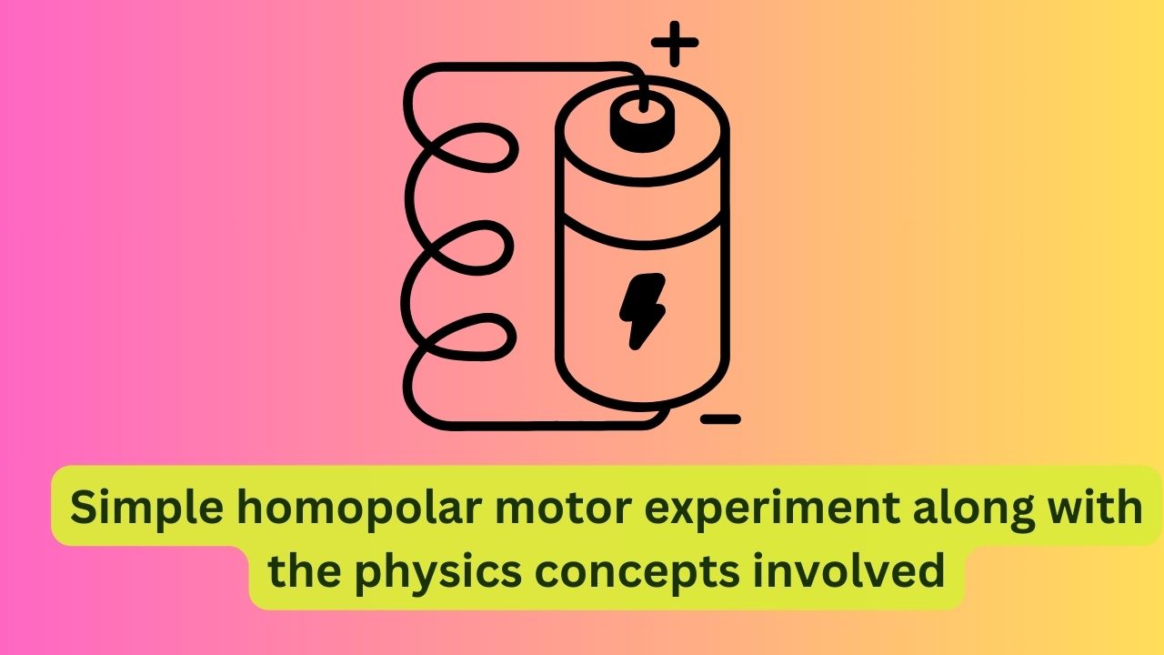
Here’s a simple homopolar motor experiment along with the physics concepts involved:
Materials Required:
- D battery
- Neodymium magnet (small and cylindrical)
- Copper wire (thin gauge)
- Paper clips (optional)
- Scissors
- Insulating tape
How to Conduct the Experiment:
- Prepare the Wire:
- Cut a piece of copper wire measuring about 10-15 centimeters in length.
- Strip the insulation from both ends of the wire, leaving about 1 centimeter of bare wire exposed.
- Construct the Motor:
- Place the D battery on a flat surface.
- Bend the wire into a U-shape with one end pointing downward and the other end forming a loop above the battery.
- Attach the neodymium magnet to the bottom of the wire loop using insulating tape, ensuring that the magnet can spin freely.
- Test the Motor:
- Carefully balance the wire on top of the battery, making sure that the looped end with the magnet is directly above the battery.
- Watch as the magnet begins to spin when the looped end of the wire makes contact with the battery terminal.
- Optional: Enhance Stability (Paper Clips):
- To enhance stability, you can attach paper clips to the ends of the wire that rest on the battery terminals. This helps maintain contact and stability during rotation.
Physics Concepts:
- Homopolar Motor Principle: The homopolar motor operates based on the principle of electromagnetism. When a current flows through a conductor (the wire) in the presence of a magnetic field (created by the magnet), a force is exerted on the wire, causing it to move.
- Fleming’s Left-Hand Rule: The direction of motion of the wire (and consequently, the rotation of the magnet) can be determined using Fleming’s left-hand rule. When the thumb of the left hand points in the direction of the magnetic field (from the north pole to the south pole), the index finger points in the direction of the current (conventional current, from positive to negative), and the middle finger points in the direction of motion (force) experienced by the wire.
- Electromagnetic Induction: As the wire makes contact with the battery terminals, a current flows through the wire due to the potential difference (voltage) provided by the battery. This current interacts with the magnetic field produced by the magnet, resulting in the generation of a force that causes the wire (and the attached magnet) to spin.
- Conservation of Angular Momentum: As the magnet spins, it demonstrates the conservation of angular momentum, which states that angular momentum is conserved when no external torque acts on a system. In this case, the spinning motion of the magnet persists due to the absence of significant external forces resisting its motion.
- Applications: Although a simple experiment, homopolar motors have practical applications in devices like electric generators and some types of motors, where the basic principles of electromagnetism are utilized to convert electrical energy into mechanical motion (and vice versa).
By conducting this experiment, students can gain hands-on experience with electromagnetism and basic principles of physics while creating a simple but fascinating motor.


No responses yet